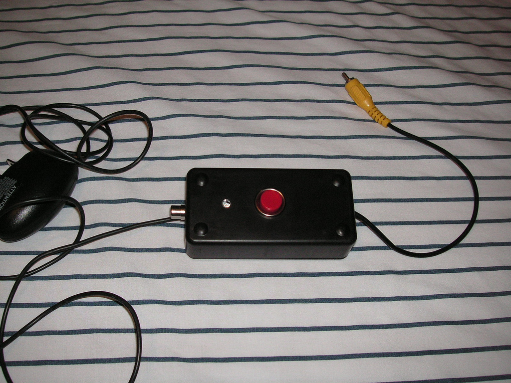
At church, we have a projector device that is hooked up to the computer that allows us to show words to a song or a video. The problem is the VGA to composite converter we have does not have a button to black out the projector. So, when I go to get a video ready to be shown, the whole congregation sees what I’m doing.
My solution was to take an arduino and build a device that would sit in the middle of the converter and projector, and allow me to black out the projector with a push button. There are several other solutions to this problem, but this seemed like the most fun. The project was named Boduino because it is a BlackOut arDUINO.
Parts
1x 5v SPDT 1A reed relay. I got mine from futurlec; JRC-23F-05
1x momentary push button. Something like this should work.
1x RBBB Arduino from Modern Device Company
1x 10k ohm resistor
1x 1k ohm resistor
1x 330 ohm resistor
1x 1N914 diode. Really most diodes would work for this.
1x common cathode RGB LED or 1x green and 1x blue LED
2x gold plated panel mount RCA jacks. I actually used one RCA jack and a cut RCA cable.
1x male to male RCA cable
1x 4x2x1 project box from RadioShack
1x Dual mini board with 213 holes from RadioShack
1x 400mA 5v/9v DC adapter
Optional:
panel mount DC jack
It should be noted that you do not have to match these parts exactly. Everything can be changed except for the resistor values. Try to get as many parts as you can from one distributer. Pay close attention to the actual size of the parts, because you could end up buying something that won’t fit (like the first push button I bought).
Schematic
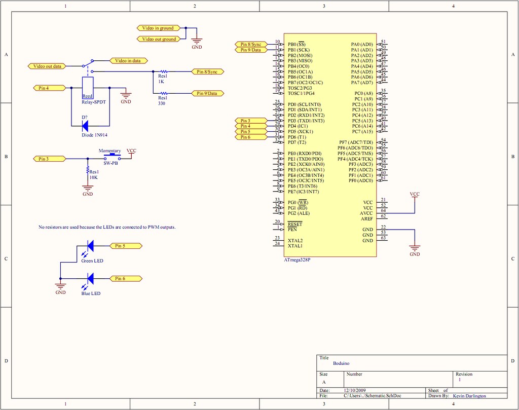
Boduino schematic
You can download the PDF of the schematic here: boduino-schematic
You can ignore the atmega328p chip on the right and just hook up your arduino to the pins I specified. Unless you know what you’re doing, then you can do what you want.
Assembly
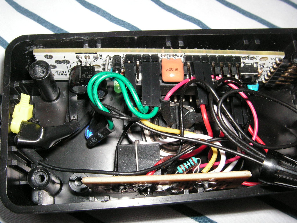
Inside boduino
First, I recommend that you put the components together on a breadboard and test it out on your TV. If you bought the same relay I did, then you will not be able to hook it up to the breadboard directly. You can either use small gauge wire and wrap it around the terminals of the relay, or you can do your testing in stages. By testing in stages, I mean just hook the TV up to the arduino without the relay and make sure that your TV is blacked out (hopefully, your TV will indicate to you if there is no signal by a message or a blue screen). Then hook up an LED in place of the relay and make sure that pressing the push button switches the LED on and off.
The hardest part of this project was soldering to the PCB board.

Boduino PCB
I hooked up all the VCC and GND terminals together in one big soldering glob. At one point I no longer felt like adding to the glob so I decided to just solder one wire, and then connect all other wires that needed VCC or GND to that particular wire.
Think about how you’re going to place your components. Try to make it as compact as possible, because space is scarce.
**Note: **If you get the same relay as me, be cautious about how that relay is designed. The VCC and GND terminals are not where you think they would be. These terminals are actually in the middle of the relay. Here is the datasheet for the relay I used. If you are still unsure, use a resistance meter. If it shows close to 0 ohms then that is a switch contact. If it shows 100+ ohms, then that is VCC and GND.
I decided not to attach the headers in the recommended way to my RBBB arduino. I attached them on the opposite side so I could connect components using the female-female jumper wires. This was also necessary to make it fit into the project box.

RBBB Arduino
I didn’t want to solder too many things because I figured I would have to change some things after I tested it.
Now, the second hardest thing was drilling and modifying the project box to get the components to fit. The button I used made fitting components a little difficult. I would suggest using the smallest button that you feel comfortable with. I wanted a good sized button so it would be easy to hit if in a panic.
On the ceiling of the project box, there are screw hole mounts used to screw in a PCB. One of these prevented the RBBB from going far enough down to close the bottom of the box.
Inside boduino
In the picture above, you can see that screw mount hole just to the left of the main screw hole (bottom right of project box). I used a dremel tool to flatten the one on the top left out. You’ll also notice that there is a connection from the main box to the main screw hole. This little piece of plastic was preventing me from inserting the RBBB perfectly. I also used the dremel to take this out on the top left.
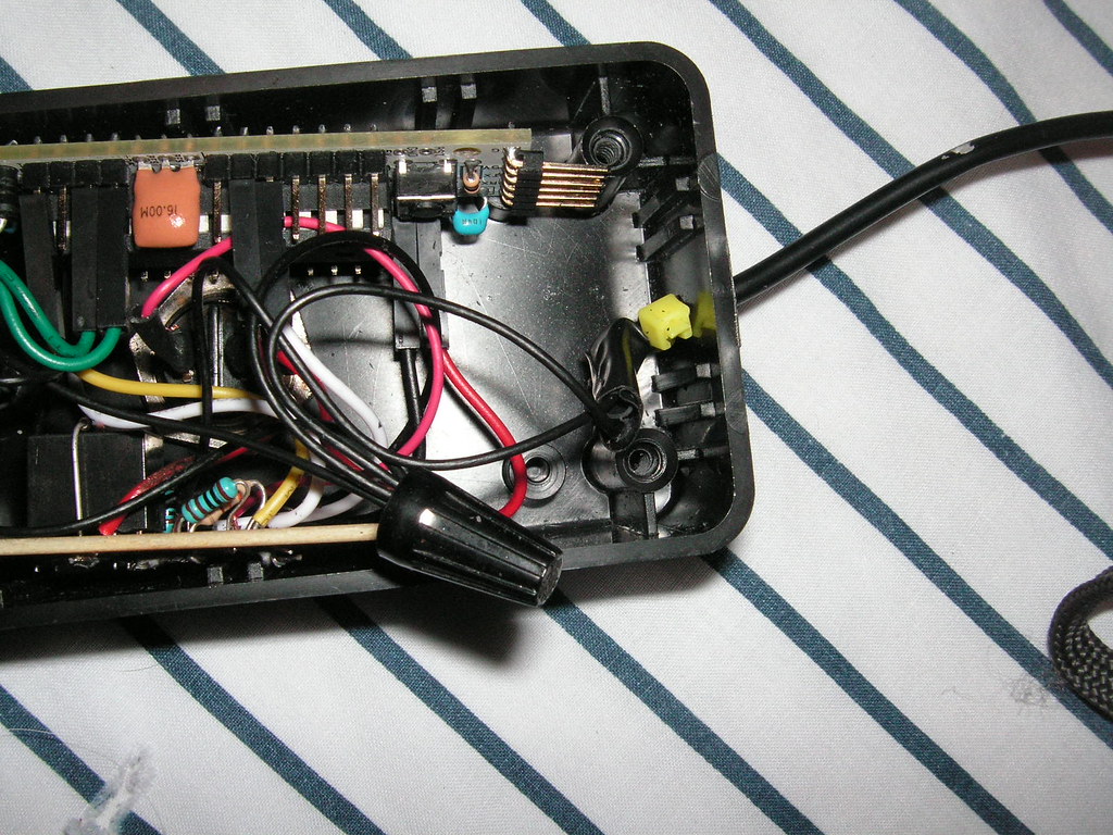
Attaching the RGB LED was pretty easy. I first thought that I would have to glue it into the box or have it poking out far. Instead, I drilled a hole slightly smaller than the LED itself, and then I forced it in there. That LED will not come out unless someone hammers it.
Instead of using a panel mount DC jack, I opted to just drill a hole and attach the DC power permanently. I happened to get a cell phone charger from my brother that worked for this purpose.
Finally, I used cable tie wraps to prevent the wires from being pulled on.
Code
Get it here: sketch_boduino.pde.
It is important to note that this code outputs a PAL signal. This seemed to work on all my TVs and the projector. I couldn’t for the life of me get any NTSC code to work. I’ve downloaded about 5 people’s code and even tried to do it myself following the specification. All I got was a blue screen (no signal).
Conclusion
I know the information here isn’t well thought out or presented. I did not plan on publishing this device when I was making it, so I took pictures after it was all together. But, you should get an idea of how everything works and how it was put together. I’ll be happy to answer any questions that anyone would have.
Known bugs
If you hook boduino up to a TV, you can see the vertical refresh line. I didn’t care to fix this because it is absolutely invisible on the projector. Any thoughts would be appreciated.
On the projector, there is a bright green line visible at the top. This is strange to me because I do not see this on any of my TVs. Luckily, in my situation, the green line is outputting on a black background, so you can’t really see it. I have a suspicion that if I get NTSC working, then this problem would go away.
Sometimes when you switch to blackout, the projector will start to search as if it lost a signal. This is very rare and when it happens it quickly goes back to being blacked out. I don’t think the projector likes interrupting an NTSC signal with a PAL one. Luckily the projector was designed well enough not to complain most of the time.
Notes
I used 1 RCA jack and a cut RCA cable. I suggest you use 2 RCA jacks and just use a male-to-male RCA cable. That way you can support any kind of female/male input/output RCA. In my design, the female RCA is the output and the male RCA is input (yes, that is backwards from the norm).
Use shrink wrap everywhere. Everything is packed in tight and wires may touch each other.
It would be cool if boduino could support both PAL and NTSC signals. I might have to look at the tellymate code to achieve this.

Load Comments